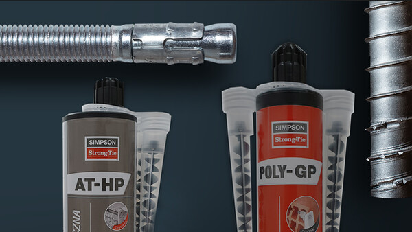
AT-HP

Harsen met hoge sterkte voor multimaterialen

Zwaar betonhars AT-HP is geschikt voor het bevestigen van betonijzers, draadstangen in gescheurd en ongescheurd beton en C20/25 tot C50/60.

CE-Markering
ETA
Brand
Binner
Buiten
Dist. bord et entraxe faible

Product Details

Afbeeldingen

Kenmerken

Materiaal

  • Styreenvrij methacrylaathars,
  • Draadstang : elektrolytisch verzinkt staal en rvs A4-70.

Voordelen

  • Hoge hechtsterkte in beton en metselwerk,
  • Uitstekend gedrag in vochtige en/of natte boorgaten,
  • Brandwerend,
  • Twee ETA's voor draadstangen op beton en metselwerk,
  • Eén ETA voor inspannen van betonijzers.

Toepassing

Ondergrond

  • Beton, cellenbeton,
  • Volle en holle baksteen,
  • Volle en holle Bouwsteen.

Toepassingsgebieden

  • Inspannen van betonijzers,
  • Bevestigen van ankerstangen in beton en metselwerk,
  • Balkons,
  • Gevel, rekken.

Technische gegevens

Références

Referentie Product information
Grey color Beige color Content [ml] Weight [kg] Packaging qty [pcs]
ATHP300G-FRx-3000.57512
ATHP420G-FRx-4200.82812

Design resistance – Tension – NRd [kN] – hef = 8d – Carbon steel 5.8

Table "Design resistance – Tension – NRd [kN] – hef = 8d – Carbon steel 5.8" cannot be displayed : no references available.

Concrete :
1. The design loads have been calculated using the partial safety factors for resistances stated in ETA-approval(s). The loading figures are valid for unreinforced concrete and reinforced concrete with a rebar spacing s ≥ 15 cm (any diameter) or with a rebar spacing s ≥ 10 cm, if the rebar diameter is 10mm or smaller.
2. The figures for shear are based on a single anchor without influence of concrete edges. For anchorages close to edges (c ≤ max [10 hef; 60d]) the concrete edge failure shall be checked per ETAG 001, Annex C, design method A.
3. Concrete is considered non-cracked when the tensile stress within the concrete is\sigmaL +\sigmaR ≤ 0. In the absence of detailed verification\sigmaR = 3 N/mm² can be assumed (\sigmaL equals the tensile stress within the concrete induced by external loads, anchors loads included).


Design resistance – Tension – NRd [kN] – hef = 12d – Carbon steel 5.8

Table "Design resistance – Tension – NRd [kN] – hef = 12d – Carbon steel 5.8" cannot be displayed : no references available.

Concrete :
1. The design loads have been calculated using the partial safety factors for resistances stated in ETA-approval(s). The loading figures are valid for unreinforced concrete and reinforced concrete with a rebar spacing s ≥ 15 cm (any diameter) or with a rebar spacing s ≥ 10 cm, if the rebar diameter is 10mm or smaller.
2. The figures for shear are based on a single anchor without influence of concrete edges. For anchorages close to edges (c ≤ max [10 hef; 60d]) the concrete edge failure shall be checked per ETAG 001, Annex C, design method A.
3. Concrete is considered non-cracked when the tensile stress within the concrete is\sigmaL +\sigmaR ≤ 0. In the absence of detailed verification\sigmaR = 3 N/mm² can be assumed (\sigmaL equals the tensile stress within the concrete induced by external loads, anchors loads included).


Design resistance – Tension – NRd [kN] – hef = 8d – Stainless steel A4-70

Table "Design resistance – Tension – NRd [kN] – hef = 8d – Stainless steel A4-70" cannot be displayed : no references available.

Concrete :
1. The design loads have been calculated using the partial safety factors for resistances stated in ETA-approval(s). The loading figures are valid for unreinforced concrete and reinforced concrete with a rebar spacing s ≥ 15 cm (any diameter) or with a rebar spacing s ≥ 10 cm, if the rebar diameter is 10mm or smaller.
2. The figures for shear are based on a single anchor without influence of concrete edges. For anchorages close to edges (c ≤ max [10 hef; 60d]) the concrete edge failure shall be checked per ETAG 001, Annex C, design method A.
3. Concrete is considered non-cracked when the tensile stress within the concrete is\sigmaL +\sigmaR ≤ 0. In the absence of detailed verification\sigmaR = 3 N/mm² can be assumed (\sigmaL equals the tensile stress within the concrete induced by external loads, anchors loads included).


Design resistance – Tension – NRd [kN] – hef = 12d – Stainless steel A4-70

Table "Design resistance – Tension – NRd [kN] – hef = 12d – Stainless steel A4-70" cannot be displayed : no references available.

Concrete :
1. The design loads have been calculated using the partial safety factors for resistances stated in ETA-approval(s). The loading figures are valid for unreinforced concrete and reinforced concrete with a rebar spacing s ≥ 15 cm (any diameter) or with a rebar spacing s ≥ 10 cm, if the rebar diameter is 10mm or smaller.
2. The figures for shear are based on a single anchor without influence of concrete edges. For anchorages close to edges (c ≤ max [10 hef; 60d]) the concrete edge failure shall be checked per ETAG 001, Annex C, design method A.
3. Concrete is considered non-cracked when the tensile stress within the concrete is\sigmaL +\sigmaR ≤ 0. In the absence of detailed verification\sigmaR = 3 N/mm² can be assumed (\sigmaL equals the tensile stress within the concrete induced by external loads, anchors loads included).


Design resistance – Shear – VRd [kN] – hef = 8d – Carbon steel 5.8

Table "Design resistance – Shear – VRd [kN] – hef = 8d – Carbon steel 5.8" cannot be displayed : no references available.

Concrete :
1. The design loads have been calculated using the partial safety factors for resistances stated in ETA-approval(s). The loading figures are valid for unreinforced concrete and reinforced concrete with a rebar spacing s ≥ 15 cm (any diameter) or with a rebar spacing s ≥ 10 cm, if the rebar diameter is 10mm or smaller.
2. The figures for shear are based on a single anchor without influence of concrete edges. For anchorages close to edges (c ≤ max [10 hef; 60d]) the concrete edge failure shall be checked per ETAG 001, Annex C, design method A.
3. Concrete is considered non-cracked when the tensile stress within the concrete is\sigmaL +\sigmaR ≤ 0. In the absence of detailed verification\sigmaR = 3 N/mm² can be assumed (\sigmaL equals the tensile stress within the concrete induced by external loads, anchors loads included).


Design resistance – Shear – VRd [kN] – hef = 12d – Carbon steel 5.8

Table "Design resistance – Shear – VRd [kN] – hef = 12d – Carbon steel 5.8" cannot be displayed : no references available.

Concrete :
1. The design loads have been calculated using the partial safety factors for resistances stated in ETA-approval(s). The loading figures are valid for unreinforced concrete and reinforced concrete with a rebar spacing s ≥ 15 cm (any diameter) or with a rebar spacing s ≥ 10 cm, if the rebar diameter is 10mm or smaller.
2. The figures for shear are based on a single anchor without influence of concrete edges. For anchorages close to edges (c ≤ max [10 hef; 60d]) the concrete edge failure shall be checked per ETAG 001, Annex C, design method A.
3. Concrete is considered non-cracked when the tensile stress within the concrete is\sigmaL +\sigmaR ≤ 0. In the absence of detailed verification\sigmaR = 3 N/mm² can be assumed (\sigmaL equals the tensile stress within the concrete induced by external loads, anchors loads included).


Design resistance – Shear – VRd [kN] – hef = 8d – Stainless steel A4-70

Table "Design resistance – Shear – VRd [kN] – hef = 8d – Stainless steel A4-70" cannot be displayed : no references available.

Concrete :
1. The design loads have been calculated using the partial safety factors for resistances stated in ETA-approval(s). The loading figures are valid for unreinforced concrete and reinforced concrete with a rebar spacing s ≥ 15 cm (any diameter) or with a rebar spacing s ≥ 10 cm, if the rebar diameter is 10mm or smaller.
2. The figures for shear are based on a single anchor without influence of concrete edges. For anchorages close to edges (c ≤ max [10 hef; 60d]) the concrete edge failure shall be checked per ETAG 001, Annex C, design method A.
3. Concrete is considered non-cracked when the tensile stress within the concrete is\sigmaL +\sigmaR ≤ 0. In the absence of detailed verification\sigmaR = 3 N/mm² can be assumed (\sigmaL equals the tensile stress within the concrete induced by external loads, anchors loads included).


Design resistance – Shear - VRd [kN] – hef = 12d – Stainless steel A4-70

Table "Design resistance – Shear - VRd [kN] – hef = 12d – Stainless steel A4-70" cannot be displayed : no references available.

Concrete :
1. The design loads have been calculated using the partial safety factors for resistances stated in ETA-approval(s). The loading figures are valid for unreinforced concrete and reinforced concrete with a rebar spacing s ≥ 15 cm (any diameter) or with a rebar spacing s ≥ 10 cm, if the rebar diameter is 10mm or smaller.
2. The figures for shear are based on a single anchor without influence of concrete edges. For anchorages close to edges (c ≤ max [10 hef; 60d]) the concrete edge failure shall be checked per ETAG 001, Annex C, design method A.
3. Concrete is considered non-cracked when the tensile stress within the concrete is\sigmaL +\sigmaR ≤ 0. In the absence of detailed verification\sigmaR = 3 N/mm² can be assumed (\sigmaL equals the tensile stress within the concrete induced by external loads, anchors loads included).


Design resistance – Bending moment – MRd [Nm] – Concrete

Table "Design resistance – Bending moment – MRd [Nm] – Concrete" cannot be displayed : no references available.

Concrete :
1. The design loads have been calculated using the partial safety factors for resistances stated in ETA-approval(s). The loading figures are valid for unreinforced concrete and reinforced concrete with a rebar spacing s ≥ 15 cm (any diameter) or with a rebar spacing s ≥ 10 cm, if the rebar diameter is 10mm or smaller.
2. The figures for shear are based on a single anchor without influence of concrete edges. For anchorages close to edges (c ≤ max [10 hef; 60d]) the concrete edge failure shall be checked per ETAG 001, Annex C, design method A.
3. Concrete is considered non-cracked when the tensile stress within the concrete is\sigmaL +\sigmaR ≤ 0. In the absence of detailed verification\sigmaR = 3 N/mm² can be assumed (\sigmaL equals the tensile stress within the concrete induced by external loads, anchors loads included).


Design resistance – Tension – NRd [kN] – Rebar

Table "Design resistance – Tension – NRd [kN] – Rebar" cannot be displayed : no references available.

Design resistance – Shear – VRd [kN] – Rebar

Table "Design resistance – Shear – VRd [kN] – Rebar" cannot be displayed : no references available.

Design resistance – Bending moment – MRd [Nm] – Rebar

Table "Design resistance – Bending moment – MRd [Nm] – Rebar" cannot be displayed : no references available.

Installatie

Installatie

Plaatsingstijd

Morteltemperatuur
[°C]
Ondersteuning temperatuur
[°C]
Praktische gebruiksduur
[min]
Uithardingstijd, droog / nat beton
[h; min]
+ 5°C- 5°C naar - 1°C15 min9 h
+ 5°C0°C naar 4°C12 min4 h
+ 5°C5°C naar 9°C9 min1,5 h
+ 10°C10°C naar 19°C4 min60 min
+ 20°C20°C naar 29°C1 min30 min
+ 30°C30°C en hoger< 1 min20 min

Drilling methods

BetonKlopboren
BaksteenDraaiboren
CellenbetonKlopboren

Installation parameters – Concrete

Table "Installation parameters – Concrete" cannot be displayed : no references available.

Spacing, edge distances and member thickness - Concrete

Table "Spacing, edge distances and member thickness - Concrete" cannot be displayed : no references available.

Installation parameters – Rebar

Table "Installation parameters – Rebar" cannot be displayed : no references available.

Spacing, edge distances and member thickness – Rebar

Table "Spacing, edge distances and member thickness – Rebar" cannot be displayed : no references available.

Verwante producten

Online kopen

Geen artikelen beschikbaar.

Contact

Simpson Strong-Tie Frankrijk

Simpson Strong-Tie

ZAC des 4 Chemins
85400 Sainte-Gemme-la-Plaine
Frankrijk