Hars voor multimaterialen
Chemische verankering voor middelzware belasting in vol en hol metselwerk.
Product Details
Kenmerken
Materiaal
- Styreenvrij polyesterhars,
- Draadstang LMAS : elektrolytisch verzinkt staal en rvs A4-70.
Voordelen
- Snel uithardend : tijdwinst voor de gebruiker,
- Geschikt voor binnengebruik,
- Uitstekende duurzaamheid.
Toepassing
Ondergrond
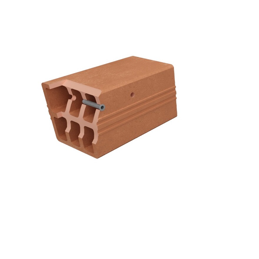
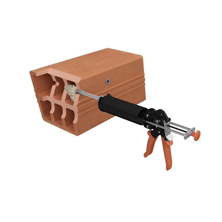
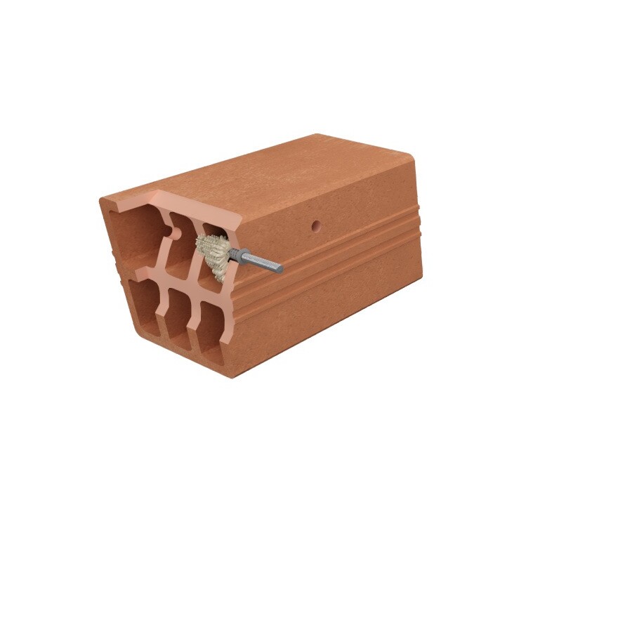
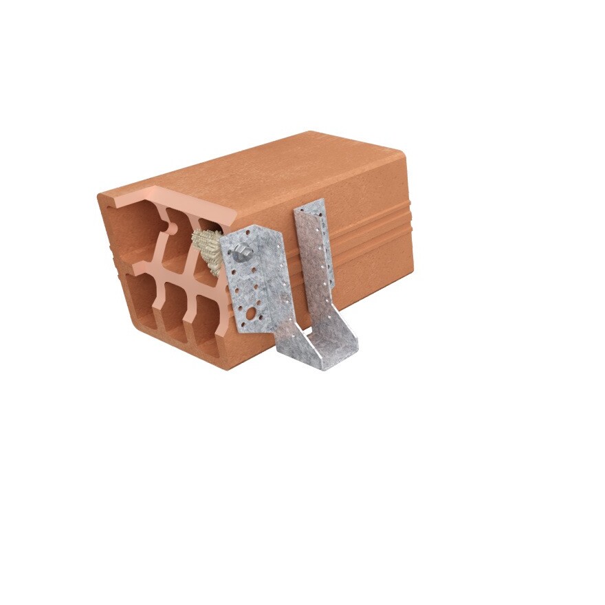
- Vol en hol metselwerk.
Toepassingsgebieden
- Rolluiken, luikhengsels,
- Airconditioners,
- Antennes,
- Waterverwarmers.
Technische gegevens
Références
| Referentie | Product information | ||||
|---|---|---|---|---|---|
| Grey color | Beige color | Content [ml] | Weigth [kg] | Packaging qty [pcs] | |
| POLYGP300G-FR | x | - | 300 | 0.586 | 12 |
| POLYGP300B-FR | - | x | 300 | 0.586 | 12 |
| POLYGP420B-FR | - | x | 420 | 0.842 | 12 |
Design resistance – Tension – NRd [kN] – Carbon steel 5.8
Concrete :
1. The design loads have been calculated using the partial safety factors for resistances stated in ETA-approval(s). The loading figures are valid for unreinforced concrete and reinforced concrete with a rebar spacing s ≥ 15 cm (any diameter) or with a rebar spacing s ≥ 10 cm, if the rebar diameter is 10mm or smaller.
2. The figures for shear are based on a single anchor without influence of concrete edges. For anchorages close to edges (c ≤ max [10 hef; 60d]) the concrete edge failure shall be checked per ETAG 001, Annex C, design method A.
3. Concrete is considered non-cracked when the tensile stress within the concrete is\sigmaL +\sigmaR ≤ 0. In the absence of detailed verification\sigmaR = 3 N/mm² can be assumed (\sigmaL equals the tensile stress within the concrete induced by external loads, anchors loads included).
Design resistance – Tension – NRd [kN] – Stainless steel A4-70
Concrete :
1. The design loads have been calculated using the partial safety factors for resistances stated in ETA-approval(s). The loading figures are valid for unreinforced concrete and reinforced concrete with a rebar spacing s ≥ 15 cm (any diameter) or with a rebar spacing s ≥ 10 cm, if the rebar diameter is 10mm or smaller.
2. The figures for shear are based on a single anchor without influence of concrete edges. For anchorages close to edges (c ≤ max [10 hef; 60d]) the concrete edge failure shall be checked per ETAG 001, Annex C, design method A.
3. Concrete is considered non-cracked when the tensile stress within the concrete is\sigmaL +\sigmaR ≤ 0. In the absence of detailed verification\sigmaR = 3 N/mm² can be assumed (\sigmaL equals the tensile stress within the concrete induced by external loads, anchors loads included).
Design resistance – Shear – VRd [kN] – Carbon steel 5.8
Concrete :
1. The design loads have been calculated using the partial safety factors for resistances stated in ETA-approval(s). The loading figures are valid for unreinforced concrete and reinforced concrete with a rebar spacing s ≥ 15 cm (any diameter) or with a rebar spacing s ≥ 10 cm, if the rebar diameter is 10mm or smaller.
2. The figures for shear are based on a single anchor without influence of concrete edges. For anchorages close to edges (c ≤ max [10 hef; 60d]) the concrete edge failure shall be checked per ETAG 001, Annex C, design method A.
3. Concrete is considered non-cracked when the tensile stress within the concrete is\sigmaL +\sigmaR ≤ 0. In the absence of detailed verification\sigmaR = 3 N/mm² can be assumed (\sigmaL equals the tensile stress within the concrete induced by external loads, anchors loads included).
Design resistance – Shear – VRd [kN] – Stainless steel A4-70
Concrete :
1. The design loads have been calculated using the partial safety factors for resistances stated in ETA-approval(s). The loading figures are valid for unreinforced concrete and reinforced concrete with a rebar spacing s ≥ 15 cm (any diameter) or with a rebar spacing s ≥ 10 cm, if the rebar diameter is 10mm or smaller.
2. The figures for shear are based on a single anchor without influence of concrete edges. For anchorages close to edges (c ≤ max [10 hef; 60d]) the concrete edge failure shall be checked per ETAG 001, Annex C, design method A.
3. Concrete is considered non-cracked when the tensile stress within the concrete is\sigmaL +\sigmaR ≤ 0. In the absence of detailed verification\sigmaR = 3 N/mm² can be assumed (\sigmaL equals the tensile stress within the concrete induced by external loads, anchors loads included).
Design resistance – Bending moment – MRd [Nm]
Concrete :
1. The design loads have been calculated using the partial safety factors for resistances stated in ETA-approval(s). The loading figures are valid for unreinforced concrete and reinforced concrete with a rebar spacing s ≥ 15 cm (any diameter) or with a rebar spacing s ≥ 10 cm, if the rebar diameter is 10mm or smaller.
2. The figures for shear are based on a single anchor without influence of concrete edges. For anchorages close to edges (c ≤ max [10 hef; 60d]) the concrete edge failure shall be checked per ETAG 001, Annex C, design method A.
3. Concrete is considered non-cracked when the tensile stress within the concrete is\sigmaL +\sigmaR ≤ 0. In the absence of detailed verification\sigmaR = 3 N/mm² can be assumed (\sigmaL equals the tensile stress within the concrete induced by external loads, anchors loads included).
Design resistance – hef = 80 mm (≤ M8) or 85 mm (≥ M10) – Carbon steel ≥ 4.6 / Stainless steel ≥ A2-70
Masonry :
| Compressive strength fb [N/mm²] | Bulk density ρ [kg/m3] | |
| Solid clay masonry | ≥ 18 | ≥ 1600 |
| Hollow masonry | ≥ 6 | ≥ 900 |
1. The design resistances have been calculated using the partial safety factors for resistances stated in ETA-approval(s).
2. The recommended loads have been calculated using the partial safety factors for resistances stated in ETA-approval(s) and with a partial safety factor for actions of γF=1.4.
3. For combined tension and shear loads or anchor groups and/or in case of edge influence, a calculation acc. TR 054, design method A shall be performed. For details see ETA - assessment(s)
4. Temperature range: -40°C/+40°C (Tmlp = +24°C)
5. Coefficiant factor β for in situ tests acc. ETAG 029 see ETA-19/0642; Annex C2
6. Displacements under service load see ETA-19/0642; Annex C2 & C3
Design resistance – Bending moment – MRd [Nm]
Masonry :
| Compressive strength fb [N/mm²] | Bulk density [kg/m3] | |
| Solid clay masonry | ≥ 18 | ≥ 1600 |
| Hollow masonry | ≥ 6 | ≥ 900 |
1. The design resistances have been calculated using the partial safety factors for resistances stated in ETA-approval(s).
2. The recommended loads have been calculated using the partial safety factors for resistances stated in ETA-approval(s) and with a partial safety factor for actions of γF=1.4.
3. For combined tension and shear loads or anchor groups and/or in case of edge influence, a calculation acc. TR 054, design method A shall be performed. For details see ETA - assessment(s)
4. Temperature range: -40°C/+40°C (Tmlp = +24°C)
5. Coefficiant factor β for in situ tests acc. ETAG 029 see ETA-19/0642; Annex C2
6. Displacements under service load see ETA-19/0642; Annex C2 & C3
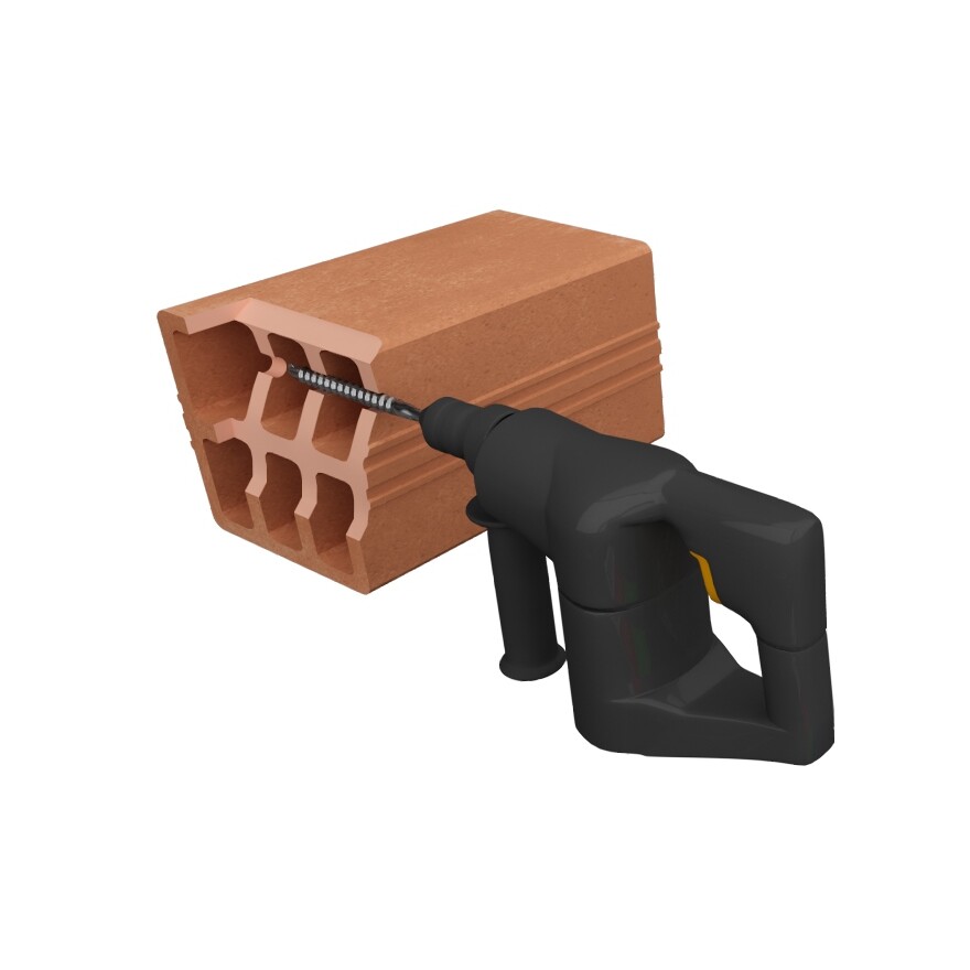
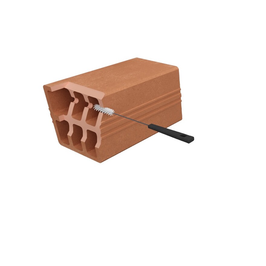
Installatie
Installatie
Plaatsingstijd
| Temperatuur [°C] | -5 | 0 | 5 | 10 | 15 | 20 | 30 |
| Verwerkingstijd | 25min | 15min | 12min | 8min | 7min | 4min | 2min |
| Belastbaar na | 4.00 | 3.00 | 2.30 | 1.15 | 55min | 30min | 20min |
