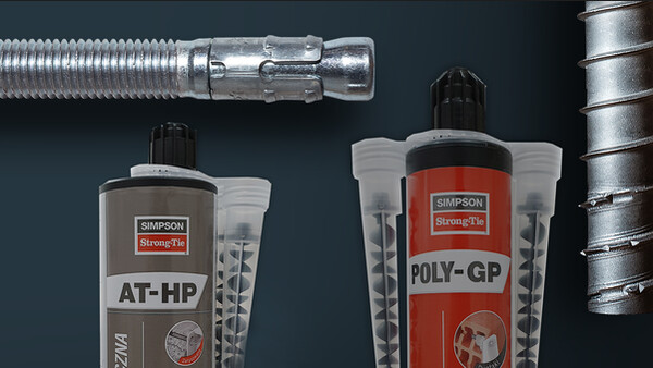

AT-HP PLUS
Hars voor multimaterialen met plaatsingsindicatie
Dit chemisch verankeringshars AT-HP Plus is geschikt voor 100% van de courante toepassingen op hol en vol metselwerk. Het kan veilig binnen worden gebruikt (COV A+) en waarborgt een eenvoudige en perfecte bevestiging dankzij een exclusieve innovatie: de plaatsingsindicatie Simpson Strong-Tie.
CE-Markering
ETA
Brand
Binner
Buiten
Dist. bord et entraxe faible

Product Details
Afbeeldingen


Kenmerken
Materiaal
- Styreenvrij methacrylaathars.
- Draadstang: elektrolytisch verzinkt staal en rvs A4-70.
Voordelen
- Hoge hechtsterkte in beton en metselwerk.
- Uitstekend gedrag in vochtige en/of natte boorgaten.
- Brandwerend.
- Twee ETA's voor draadstangen op beton en metselwerk.
- Eén ETA voor inspannen van betonijzers.
Toepassing
Ondergrond
- Beton, cellenbeton.
- Volle en holle baksteen.
- Volle en holle Bouwsteen.
Toepassingsgebieden
- Inspannen van betonijzers.
- Bevestigen van ankerstangen in beton en metselwerk.
- Balkons.
- Gevel, rekken.
Discontinued Products
Variant Status Details
There are variants of this product family which have been discontinued and are out of production.
phased out (has Variants which were phased out)Technische gegevens
Références
| Referentie | Product information | ||||
|---|---|---|---|---|---|
| Grey color | Beige color | Content [ml] | Weigth [kg] | Packaging qty [pcs] | |
| ATHP300PLUSG-FR | x | - | 300 | 0.575 | 12 |
| ATHP420PLUSG-FR | x | - | 420 | 0.828 | 12 |
Design resistance – Tension – NRd [kN] – hef = 8d – Carbon steel 5.8
| Referentie | Design resistance – hef = 8d – Carbon steel 5.8 | |||||||
|---|---|---|---|---|---|---|---|---|
| Tension - NRd [kN] | ||||||||
| Cracked concrete | Non-cracked concrete | |||||||
| C20/25 | C30/37 | C40/50 | C50/60 | C20/25 | C30/37 | C40/50 | C50/60 | |
| AT-HP PLUS + LMAS M8 | - | - | - | - | 10.7 | 12 | 12 | 12 |
| AT-HP PLUS + LMAS M10 | - | - | - | - | 15.9 | 17.8 | 19.3 | 19.3 |
| AT-HP PLUS + LMAS M12 | 8.4 | 8.8 | 9 | 9.2 | 21.7 | 24.3 | 26.7 | 28 |
| AT-HP PLUS + LMAS M16 | 15 | 15.6 | 16.1 | 16.4 | 34.3 | 38.4 | 42.2 | 44.6 |
| AT-HP PLUS + LMAS M20 | - | - | - | - | 50.2 | 56.3 | 61.8 | 65.3 |
| AT-HP PLUS + LMAS M24 | - | - | - | - | 67.5 | 75.6 | 83.1 | 87.8 |
Concrete :
1. The design loads have been calculated using the partial safety factors for resistances stated in ETA-approval(s). The loading figures are valid for unreinforced concrete and reinforced concrete with a rebar spacing s ≥ 15 cm (any diameter) or with a rebar spacing s ≥ 10 cm, if the rebar diameter is 10mm or smaller.
2. The figures for shear are based on a single anchor without influence of concrete edges. For anchorages close to edges (c ≤ max [10 hef; 60d]) the concrete edge failure shall be checked per ETAG 001, Annex C, design method A.
3. Concrete is considered non-cracked when the tensile stress within the concrete is\sigmaL +\sigmaR ≤ 0. In the absence of detailed verification\sigmaR = 3 N/mm² can be assumed (\sigmaL equals the tensile stress within the concrete induced by external loads, anchors loads included).
Design resistance – Tension – NRd [kN] – hef = 12d – Carbon steel 5.8
| Referentie | Design resistance – hef = 12d – Carbon steel 5.8 | |||||||
|---|---|---|---|---|---|---|---|---|
| Tension - NRd [kN] | ||||||||
| Cracked concrete | Non-cracked concrete | |||||||
| C20/25 | C30/37 | C40/50 | C50/60 | C20/25 | C30/37 | C40/50 | C50/60 | |
| AT-HP PLUS + LMAS M8 | - | - | - | - | 12 | 12 | 12 | 12 |
| AT-HP PLUS + LMAS M10 | - | - | - | - | 19.3 | 19.3 | 19.3 | 19.3 |
| AT-HP PLUS + LMAS M12 | 12.7 | 13.2 | 13.5 | 13.8 | 28 | 28 | 28 | 28 |
| AT-HP PLUS + LMAS M16 | 22.5 | 23.4 | 24.1 | 24.5 | 51.4 | 52.7 | 52.7 | 52.7 |
| AT-HP PLUS + LMAS M20 | - | - | - | - | 75.4 | 82 | 82 | 82 |
| AT-HP PLUS + LMAS M24 | - | - | - | - | 101.3 | 113.4 | 118 | 118 |
Concrete:
1. The design loads have been calculated using the partial safety factors for resistances stated in ETA-approval(s). The loading figures are valid for unreinforced concrete and reinforced concrete with a rebar spacing s ≥ 15 cm (any diameter) or with a rebar spacing s ≥ 10 cm, if the rebar diameter is 10mm or smaller.
2. The figures for shear are based on a single anchor without influence of concrete edges. For anchorages close to edges (c ≤ max [10 hef; 60d]) the concrete edge failure shall be checked per ETAG 001, Annex C, design method A.
3. Concrete is considered non-cracked when the tensile stress within the concrete is\sigmaL +\sigmaR ≤ 0. In the absence of detailed verification\sigmaR = 3 N/mm² can be assumed (\sigmaL equals the tensile stress within the concrete induced by external loads, anchors loads included).
Design resistance – Tension – NRd [kN] – hef = 8d – Stainless steel A4-70
| Referentie | Design resistance – hef = 8d – Stainless steel A4-70 | |||||||
|---|---|---|---|---|---|---|---|---|
| Tension - NRd [kN] | ||||||||
| Cracked concrete | Non-cracked concrete | |||||||
| C20/25 | C30/37 | C40/50 | C50/60 | C20/25 | C30/37 | C40/50 | C50/60 | |
| AT-HP PLUS + LMAS M8 | - | - | - | - | 10.7 | 12 | 13.2 | 13.9 |
| AT-HP PLUS + LMAS M10 | - | - | - | - | 15.9 | 17.8 | 19.6 | 20.7 |
| AT-HP PLUS + LMAS M12 | 8.4 | 8.8 | 9 | 9.2 | 21.7 | 24.3 | 26.7 | 28.2 |
| AT-HP PLUS + LMAS M16 | 15 | 15.6 | 16.1 | 16.4 | 34.3 | 38.4 | 42.2 | 44.6 |
| AT-HP PLUS + LMAS M20 | - | - | - | - | 50.2 | 56.3 | 61.8 | 65.3 |
| AT-HP PLUS + LMAS M24 | - | - | - | - | 67.5 | 75.6 | 83.1 | 87.8 |
Concrete :
1. The design loads have been calculated using the partial safety factors for resistances stated in ETA-approval(s). The loading figures are valid for unreinforced concrete and reinforced concrete with a rebar spacing s ≥ 15 cm (any diameter) or with a rebar spacing s ≥ 10 cm, if the rebar diameter is 10mm or smaller.
2. The figures for shear are based on a single anchor without influence of concrete edges. For anchorages close to edges (c ≤ max [10 hef; 60d]) the concrete edge failure shall be checked per ETAG 001, Annex C, design method A.
3. Concrete is considered non-cracked when the tensile stress within the concrete is\sigmaL +\sigmaR ≤ 0. In the absence of detailed verification\sigmaR = 3 N/mm² can be assumed (\sigmaL equals the tensile stress within the concrete induced by external loads, anchors loads included).
Design resistance – Tension – NRd [kN] – hef = 12d – Stainless steel A4-70
| Referentie | Design resistance – hef = 12d – Stainless steel A4-70 | |||||||
|---|---|---|---|---|---|---|---|---|
| Tension - NRd [kN] | ||||||||
| Cracked concrete | Non-cracked concrete | |||||||
| C20/25 | C30/37 | C40/50 | C50/60 | C20/25 | C30/37 | C40/50 | C50/60 | |
| AT-HP PLUS + LMAS M8 | - | - | - | - | 13.9 | 13.9 | 13.9 | 13.9 |
| AT-HP PLUS + LMAS M10 | - | - | - | - | 21.9 | 21.9 | 21.9 | 21.9 |
| AT-HP PLUS + LMAS M12 | 12.7 | 13.2 | 13.5 | 13.8 | 31.6 | 31.6 | 31.6 | 31.6 |
| AT-HP PLUS + LMAS M16 | 22.5 | 23.4 | 24.1 | 24.5 | 51.4 | 57.6 | 58.8 | 58.8 |
| AT-HP PLUS + LMAS M20 | - | - | - | - | 75.4 | 84.4 | 92 | 92 |
| AT-HP PLUS + LMAS M24 | - | - | - | - | 101.3 | 113.4 | 124.6 | 131.7 |
Concrete :
1. The design loads have been calculated using the partial safety factors for resistances stated in ETA-approval(s). The loading figures are valid for unreinforced concrete and reinforced concrete with a rebar spacing s ≥ 15 cm (any diameter) or with a rebar spacing s ≥ 10 cm, if the rebar diameter is 10mm or smaller.
2. The figures for shear are based on a single anchor without influence of concrete edges. For anchorages close to edges (c ≤ max [10 hef; 60d]) the concrete edge failure shall be checked per ETAG 001, Annex C, design method A.
3. Concrete is considered non-cracked when the tensile stress within the concrete is\sigmaL +\sigmaR ≤ 0. In the absence of detailed verification\sigmaR = 3 N/mm² can be assumed (\sigmaL equals the tensile stress within the concrete induced by external loads, anchors loads included).
Design resistance – Shear – VRd [kN] – hef = 8d – Carbon steel 5.8
| Referentie | Design resistance – hef = 8d – Carbon steel 5.8 | |||||||
|---|---|---|---|---|---|---|---|---|
| Shear - VRd [kN] | ||||||||
| Cracked concrete | Non-cracked concrete | |||||||
| C20/25 | C30/37 | C40/50 | C50/60 | C20/25 | C30/37 | C40/50 | C50/60 | |
| AT-HP PLUS + LMAS M8 | - | - | - | - | 7.2 | 7.2 | 7.2 | 7.2 |
| AT-HP PLUS + LMAS M10 | - | - | - | - | 12 | 12 | 12 | 12 |
| AT-HP PLUS + LMAS M12 | 16.8 | 16.8 | 16.8 | 16.8 | 16.8 | 16.8 | 16.8 | 16.8 |
| AT-HP PLUS + LMAS M16 | 30 | 31.2 | 31.2 | 31.2 | 31.2 | 31.2 | 31.2 | 31.2 |
| AT-HP PLUS + LMAS M20 | - | - | - | - | 48.8 | 48.8 | 48.8 | 48.8 |
| AT-HP PLUS + LMAS M24 | - | - | - | - | 70.4 | 70.4 | 70.4 | 70.4 |
Concrete :
1. The design loads have been calculated using the partial safety factors for resistances stated in ETA-approval(s). The loading figures are valid for unreinforced concrete and reinforced concrete with a rebar spacing s ≥ 15 cm (any diameter) or with a rebar spacing s ≥ 10 cm, if the rebar diameter is 10mm or smaller.
2. The figures for shear are based on a single anchor without influence of concrete edges. For anchorages close to edges (c ≤ max [10 hef; 60d]) the concrete edge failure shall be checked per ETAG 001, Annex C, design method A.
3. Concrete is considered non-cracked when the tensile stress within the concrete is\sigmaL +\sigmaR ≤ 0. In the absence of detailed verification\sigmaR = 3 N/mm² can be assumed (\sigmaL equals the tensile stress within the concrete induced by external loads, anchors loads included).
Design resistance – Shear – VRd [kN] – hef = 12d – Carbon steel 5.8
| Referentie | Design resistance – hef = 12d – Carbon steel 5.8 | |||||||
|---|---|---|---|---|---|---|---|---|
| Shear - VRd [kN] | ||||||||
| Cracked concrete | Non-cracked concrete | |||||||
| C20/25 | C30/37 | C40/50 | C50/60 | C20/25 | C30/37 | C40/50 | C50/60 | |
| AT-HP PLUS + LMAS M8 | - | - | - | - | 7.2 | 7.2 | 7.2 | 7.2 |
| AT-HP PLUS + LMAS M10 | - | - | - | - | 12 | 12 | 12 | 12 |
| AT-HP PLUS + LMAS M12 | 16.8 | 16.8 | 16.8 | 16.8 | 16.8 | 16.8 | 16.8 | 16.8 |
| AT-HP PLUS + LMAS M16 | 31.2 | 31.2 | 31.2 | 31.2 | 31.2 | 31.2 | 31.2 | 31.2 |
| AT-HP PLUS + LMAS M20 | - | - | - | - | 48.8 | 48.8 | 48.8 | 48.8 |
| AT-HP PLUS + LMAS M24 | - | - | - | - | 70.4 | 70.4 | 70.4 | 70.4 |
Concrete :
1. The design loads have been calculated using the partial safety factors for resistances stated in ETA-approval(s). The loading figures are valid for unreinforced concrete and reinforced concrete with a rebar spacing s ≥ 15 cm (any diameter) or with a rebar spacing s ≥ 10 cm, if the rebar diameter is 10mm or smaller.
2. The figures for shear are based on a single anchor without influence of concrete edges. For anchorages close to edges (c ≤ max [10 hef; 60d]) the concrete edge failure shall be checked per ETAG 001, Annex C, design method A.
3. Concrete is considered non-cracked when the tensile stress within the concrete is\sigmaL +\sigmaR ≤ 0. In the absence of detailed verification\sigmaR = 3 N/mm² can be assumed (\sigmaL equals the tensile stress within the concrete induced by external loads, anchors loads included).
Design resistance – Shear – VRd [kN] – hef = 8d – Stainless steel A4-70
| Referentie | Design resistance – hef = 8d – Stainless steel A4-70 | |||||||
|---|---|---|---|---|---|---|---|---|
| Shear - VRd [kN] | ||||||||
| Cracked concrete | Non-cracked concrete | |||||||
| C20/25 | C30/37 | C40/50 | C50/60 | C20/25 | C30/37 | C40/50 | C50/60 | |
| AT-HP PLUS + LMAS M8 | - | - | - | - | 8.3 | 8.3 | 8.3 | 8.3 |
| AT-HP PLUS + LMAS M10 | - | - | - | - | 12.8 | 12.8 | 12.8 | 12.8 |
| AT-HP PLUS + LMAS M12 | 16.9 | 17.6 | 18.1 | 18.4 | 19.2 | 19.2 | 19.2 | 19.2 |
| AT-HP PLUS + LMAS M16 | 30 | 31.2 | 32.1 | 32.7 | 35.3 | 35.3 | 35.3 | 35.3 |
| AT-HP PLUS + LMAS M20 | - | - | - | - | 55.1 | 55.1 | 55.1 | 55.1 |
| AT-HP PLUS + LMAS M24 | - | - | - | - | 79.5 | 79.5 | 79.5 | 79.5 |
Concrete :
1. The design loads have been calculated using the partial safety factors for resistances stated in ETA-approval(s). The loading figures are valid for unreinforced concrete and reinforced concrete with a rebar spacing s ≥ 15 cm (any diameter) or with a rebar spacing s ≥ 10 cm, if the rebar diameter is 10mm or smaller.
2. The figures for shear are based on a single anchor without influence of concrete edges. For anchorages close to edges (c ≤ max [10 hef; 60d]) the concrete edge failure shall be checked per ETAG 001, Annex C, design method A.
3. Concrete is considered non-cracked when the tensile stress within the concrete is\sigmaL +\sigmaR ≤ 0. In the absence of detailed verification\sigmaR = 3 N/mm² can be assumed (\sigmaL equals the tensile stress within the concrete induced by external loads, anchors loads included).
Design resistance – Shear – VRd [kN] – hef = 12d – Stainless steel A4-70
| Referentie | Design resistance – hef = 12d – Stainless steel A4-70 | |||||||
|---|---|---|---|---|---|---|---|---|
| Shear - VRd [kN] | ||||||||
| Cracked concrete | Non-cracked concrete | |||||||
| C20/25 | C30/37 | C40/50 | C50/60 | C20/25 | C30/37 | C40/50 | C50/60 | |
| AT-HP PLUS + LMAS M8 | - | - | - | - | 8.3 | 8.3 | 8.3 | 8.3 |
| AT-HP PLUS + LMAS M10 | - | - | - | - | 12.8 | 12.8 | 12.8 | 12.8 |
| AT-HP PLUS + LMAS M12 | 19.2 | 19.2 | 19.2 | 19.2 | 19.2 | 19.2 | 19.2 | 19.2 |
| AT-HP PLUS + LMAS M16 | 35.3 | 35.3 | 35.3 | 35.3 | 35.3 | 35.3 | 35.3 | 35.3 |
| AT-HP PLUS + LMAS M20 | - | - | - | - | 55.1 | 55.1 | 55.1 | 55.1 |
| AT-HP PLUS + LMAS M24 | - | - | - | - | 79.5 | 79.5 | 79.5 | 79.5 |
Concrete :
1. The design loads have been calculated using the partial safety factors for resistances stated in ETA-approval(s). The loading figures are valid for unreinforced concrete and reinforced concrete with a rebar spacing s ≥ 15 cm (any diameter) or with a rebar spacing s ≥ 10 cm, if the rebar diameter is 10mm or smaller.
2. The figures for shear are based on a single anchor without influence of concrete edges. For anchorages close to edges (c ≤ max [10 hef; 60d]) the concrete edge failure shall be checked per ETAG 001, Annex C, design method A.
3. Concrete is considered non-cracked when the tensile stress within the concrete is\sigmaL +\sigmaR ≤ 0. In the absence of detailed verification\sigmaR = 3 N/mm² can be assumed (\sigmaL equals the tensile stress within the concrete induced by external loads, anchors loads included).
Design resistance – Bending moment – MRd [Nm] – Concrete
| Referentie | Design resistance – Bending moment – MRd [Nm] | |
|---|---|---|
| Carbon steel 5.8 | Stainless steel A4-70 | |
| AT-HP PLUS + LMAS M8 | 15.2 | 16.7 |
| AT-HP PLUS + LMAS M10 | 29.6 | 34 |
| AT-HP PLUS + LMAS M12 | 52.8 | 59 |
| AT-HP PLUS + LMAS M16 | 133.6 | 149.4 |
| AT-HP PLUS + LMAS M20 | 260.8 | 291 |
| AT-HP PLUS + LMAS M24 | 448.8 | 502.6 |
Concrete :
1. The design loads have been calculated using the partial safety factors for resistances stated in ETA-approval(s). The loading figures are valid for unreinforced concrete and reinforced concrete with a rebar spacing s ≥ 15 cm (any diameter) or with a rebar spacing s ≥ 10 cm, if the rebar diameter is 10mm or smaller.
2. The figures for shear are based on a single anchor without influence of concrete edges. For anchorages close to edges (c ≤ max [10 hef; 60d]) the concrete edge failure shall be checked per ETAG 001, Annex C, design method A.
3. Concrete is considered non-cracked when the tensile stress within the concrete is\sigmaL +\sigmaR ≤ 0. In the absence of detailed verification\sigmaR = 3 N/mm² can be assumed (\sigmaL equals the tensile stress within the concrete induced by external loads, anchors loads included).
Design resistance – Tension – NRd [kN] – Rebar
| Referentie | Design resistance – NRd – Carbon steel 5.8 [kN] | |||||||
|---|---|---|---|---|---|---|---|---|
| Non-cracked concrete | ||||||||
| hef = 8d | hef = 12d | |||||||
| C20/25 | C30/37 | C40/50 | C50/60 | C20/25 | C30/37 | C40/50 | C50/60 | |
| AT-HP PLUS + Ø8 | 6.3 | 7 | 7.7 | 8.1 | 9.4 | 10.5 | 11.5 | 12.2 |
| AT-HP PLUS + Ø10 | 10.5 | 11.7 | 12.9 | 13.6 | 15.7 | 17.6 | 19.3 | 20.4 |
| AT-HP PLUS + Ø12 | 14.1 | 15.8 | 17.3 | 18.3 | 21.1 | 23.6 | 26 | 27.4 |
| AT-HP PLUS + Ø14 | 19.1 | 21.4 | 23.6 | 24.9 | 28.7 | 32.2 | 35.3 | 37.3 |
| AT-HP PLUS + Ø16 | 23.2 | 26 | 28.6 | 34.8 | 34.8 | 39 | 42.8 | 52.2 |
| AT-HP PLUS + Ø20 | 36.3 | 40.6 | 44.6 | 47.2 | 54.4 | 61 | 66.9 | 70.8 |
| AT-HP PLUS + Ø25 | 52.3 | 58.6 | 64.4 | 68 | 78.5 | 87.9 | 96.6 | 102.1 |
Design resistance – Shear – VRd [kN] – Rebar
| Referentie | Design resistance – VRd – Carbon steel 5.8 [kN] | |||||||
|---|---|---|---|---|---|---|---|---|
| Non-cracked concrete | ||||||||
| hef = 8d | hef = 12d | |||||||
| C20/25 | C30/37 | C40/50 | C50/60 | C20/25 | C30/37 | C40/50 | C50/60 | |
| AT-HP PLUS + Ø8 | 9.3 | 9.3 | 9.3 | 9.3 | 9.3 | 9.3 | 9.3 | 9.3 |
| AT-HP PLUS + Ø10 | 14.7 | 14.7 | 14.7 | 14.7 | 14.7 | 14.7 | 14.7 | 14.7 |
| AT-HP PLUS + Ø12 | 20.7 | 20.7 | 20.7 | 20.7 | 20.7 | 20.7 | 20.7 | 20.7 |
| AT-HP PLUS + Ø14 | 28 | 28 | 28 | 28 | 28 | 28 | 28 | 28 |
| AT-HP PLUS + Ø16 | 36.7 | 36.7 | 36.7 | 36.7 | 36.7 | 36.7 | 36.7 | 36.7 |
| AT-HP PLUS + Ø20 | 57.3 | 57.3 | 57.3 | 57.3 | 57.3 | 57.3 | 57.3 | 57.3 |
| AT-HP PLUS + Ø25 | 90 | 90 | 90 | 90 | 90 | 90 | 90 | 90 |
Design resistance – Bending moment – MRd [Nm] – Rebar
| Referentie | Design resistance – Bending moment – MRd [Nm] |
|---|---|
| AT-HP PLUS + Ø8 | 22 |
| AT-HP PLUS + Ø10 | 43.3 |
| AT-HP PLUS + Ø12 | 74.7 |
| AT-HP PLUS + Ø14 | 118.7 |
| AT-HP PLUS + Ø16 | 176.7 |
| AT-HP PLUS + Ø20 | 345.3 |
| AT-HP PLUS + Ø25 | 674.7 |
Installatie
Installatie
Plaatsingstijd
| Temperatuur [°C] | -5 | 0 | 5 | 10 | 20 | 30 |
| Verwerkingstijd | 45min | 15min | 12min | 9min | 4min | 1min |
| Belastbaar na | 9.00 | 4.00 | 1.30 | 60min | 30min | 20min |
Méthodes de perçage
| Brique pleine/Béton | perçage à percussion |
| Brique creuse | perçage rotatif |
| Béton cellulaire | perçage à percussion |

1. Gat boren.

2. Schoonborstelen.

3. Zeefhuls insteken.

4. Vullen vanaf bodemgat naar
buiten door bij het pompen
telkens één maatstreep op de
spuitmond achteruit te gaan.

5. Ankerstang licht draaiend insteken.

Fix when the curing time is reached.

1. Gat boren.

2. Boorgat reinigen door uitborstelen en uitblazen
zoals aangegeven op de patroon.

3. Gat voor de helft tot twee derde
vullen vanaf het bodemgat naar
buiten door bij het pompen telkens
één maatstreep op de spuitmond
achteruit te gaan.

4. Draadstang insteken door langzaam
van links naar rechts te draaien.
U kunt de draadstang verplaatsen of
hars toevoegen zolang de
verwerkingstijd niet bereikt is.

5. Vastzetten na het bereiken
van de uithardingstijd.
Installation parameters – Concrete
| Referentie | Installation parameters - Concrete | |||||
|---|---|---|---|---|---|---|
| Ø drilling [d0] [mm] | Max. fixture hole Ø [df] [mm] | Drilling depth (8d) [h0=hef=8d] [mm] | Drilling depth (12d) [h0=hef=12d] [mm] | Wrench size [SW] | Installation torque [Tinst] [Nm] | |
| AT-HP PLUS + LMAS M8 | 10 | 9 | 64 | 96 | 13 | 10 |
| AT-HP PLUS + LMAS M10 | 12 | 12 | 80 | 120 | 17 | 20 |
| AT-HP PLUS + LMAS M12 | 14 | 14 | 96 | 144 | 19 | 30 |
| AT-HP PLUS + LMAS M16 | 18 | 18 | 128 | 192 | 24 | 60 |
| AT-HP PLUS + LMAS M20 | 24 | 22 | 160 | 240 | 30 | 90 |
| AT-HP PLUS + LMAS M24 | 28 | 26 | 192 | 288 | 36 | 140 |
Spacing, edge distances and member thickness – Concrete
| Referentie | Spacing, edge distance and member thickness - Concrete | |||||||||
|---|---|---|---|---|---|---|---|---|---|---|
| Effective embedment depth (8d) [hef,8d] [mm] | Characteristic spacing for hef,8d [Scr,N] [mm] | Characteristic edge distance for hef,8d [ccr,N] [mm] | Min. member thickness for hef,8d [hmin] [mm] | Effective embedment depth (12d) [hef,12d] [mm] | Characteristic spacing for hef,12d [Scr,N] [mm] | Characteristic edge distance for hef,12d [ccr,N] [mm] | Min. member thickness for hef,12d [hmin] [mm] | Min. spacing [Smin] [mm] | Min. edge distance [Cmin] [mm] | |
| AT-HP PLUS + LMAS M8 | 64 | 192 | 96 | 100 | 96 | 288 | 144 | 100 | 40 | 40 |
| AT-HP PLUS + LMAS M10 | 80 | 240 | 120 | 110 | 120 | 360 | 180 | 150 | 50 | 50 |
| AT-HP PLUS + LMAS M12 | 96 | 288 | 144 | 126 | 144 | 432 | 216 | 174 | 60 | 60 |
| AT-HP PLUS + LMAS M16 | 128 | 384 | 192 | 158 | 192 | 576 | 288 | 222 | 80 | 80 |
| AT-HP PLUS + LMAS M20 | 160 | 480 | 240 | 190 | 240 | 720 | 360 | 270 | 100 | 100 |
| AT-HP PLUS + LMAS M24 | 192 | 576 | 288 | 222 | 288 | 864 | 432 | 318 | 120 | 120 |
Installation parameters – Rebar
| Referentie | Installation parameters - Rebar | ||
|---|---|---|---|
| Ø drilling [d0] [mm] | Drilling depth (8d) [h0=hef=8d] [mm] | Drilling depth (12d) [h0=hef=12d] [mm] | |
| AT-HP PLUS + Ø8 | 12 | 64 | 96 |
| AT-HP PLUS + Ø10 | 14 | 80 | 120 |
| AT-HP PLUS + Ø12 | 16 | 96 | 144 |
| AT-HP PLUS + Ø14 | 18 | 112 | 168 |
| AT-HP PLUS + Ø16 | 20 | 128 | 192 |
| AT-HP PLUS + Ø20 | 25 | 160 | 240 |
| AT-HP PLUS + Ø25 | 32 | 200 | 300 |
Spacing, edge distances and member thickness – Rebar
| Referentie | Spacing, edge distance and member thickness - Rebar | |||||||||
|---|---|---|---|---|---|---|---|---|---|---|
| Effective embedment depth (8d) [hef,8d] [mm] | Characteristic spacing for hef,8d [Scr,N] [mm] | Characteristic edge distance for hef,8d [ccr,N] [mm] | Min. member thickness for hef,8d [hmin] [mm] | Effective embedment depth (12d) [hef,12d] [mm] | Characteristic spacing for hef,12d [Scr,N] [mm] | Characteristic edge distance for hef,12d [ccr,N] [mm] | Min. member thickness for hef,12d [hmin] [mm] | Min. spacing [Smin] [mm] | Min. edge distance [Cmin] [mm] | |
| AT-HP PLUS + Ø8 | 64 | 192 | 96 | 100 | 96 | 288 | 144 | 100 | 40 | 40 |
| AT-HP PLUS + Ø10 | 80 | 240 | 120 | 110 | 120 | 360 | 180 | 150 | 50 | 50 |
| AT-HP PLUS + Ø12 | 96 | 288 | 144 | 126 | 144 | 432 | 216 | 174 | 60 | 60 |
| AT-HP PLUS + Ø14 | 112 | 336 | 168 | 148 | 168 | 504 | 252 | 204 | 70 | 70 |
| AT-HP PLUS + Ø16 | 128 | 384 | 192 | 168 | 192 | 576 | 288 | 232 | 80 | 80 |
| AT-HP PLUS + Ø20 | 160 | 480 | 240 | 210 | 240 | 720 | 360 | 290 | 100 | 100 |
| AT-HP PLUS + Ø25 | 200 | 600 | 300 | 264 | 300 | 900 | 450 | 364 | 125 | 125 |
